|
|
Power Unit 406 Rebuild
These pages once formed part of the "DNLL" website and later the "Definitive Deltics" website - many thanks to DNLL, especially Michael Timms and Brian Grey for the use of photos and information...
When 9016 "GORDON HIGHLANDER" suffered an exhaust silencer fire at Loughborough on December 3rd 1999, its No. 1 power unit (406) was damaged by the fire brigade by pouring foam down the exhaust. This was to extinguish the deep seated fire in the silencer. Unfortunately, so much foam was used that it travelled back through the exhaust system and into the power unit itself. This led to the unit becoming locked in one position, partly due to water in the cylinders and partly due to corrosion of some pistons from the chemicals in the foam. This resulted in the damaged power unit being taken to MAN B&W Paxman's works at Colchester for rectification. As will be seen from the following photographs, this operation turned into the most extensive power unit rebuild ever carried out since the end of Deltic service on BR...
|
|
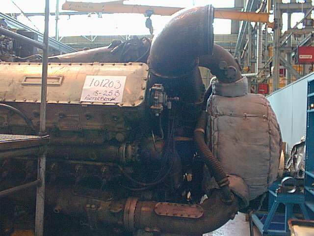
This shot shows the power unit soon after arrival at the workshops at Colchester. The unit has been given a job description number in readiness for stripping. This end of the unit shows the exhaust collector drum with the exhaust manifolds going into it. The large "elbow" pipe towards the top of the picture is the main air intake for the power unit which connects into the unit's scavenger blower below it...
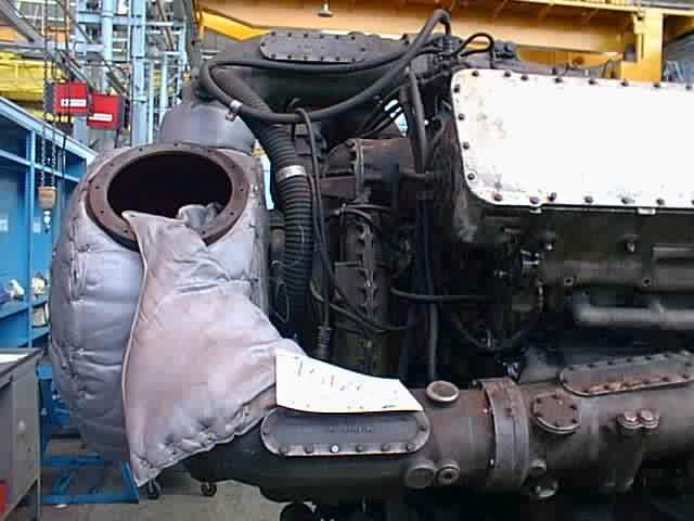
1849 - Photo: MAN B&W Paxman & courtesy of Michael Timms.This view is taken from the other side of the power unit soon after arrival at Paxmans. The large opening in the collector drum on the left of the picture would normally connect to an elbow joint and the large flexible exhaust bellows, leading to the exhaust silencer in the roof of the locomotive. To the right of the collector drum can be seen (with the bolted joint down the middle) the scavenge blower casing. The large pipe at the bottom of the picture, leading into the collector drum is an exhaust manifold...
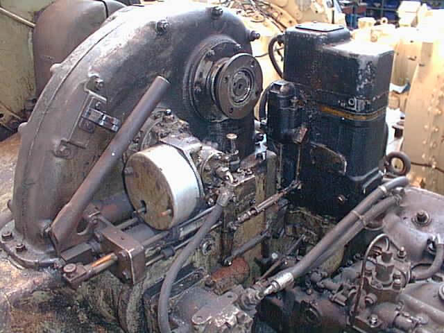
1848 - Photo: MAN B&W Paxman & courtesy of Michael Timms.This view shows the top of the power unit before stripping commenced. At the rear of the picture is the drive from the phasing gearcase to the primary prop-shaft for driving the cooling fans in the roof of the loco. On the far side of the unit and to the right of the picture is the power unit governor, which keeps the speed of the unit regular. On the bottom right of the picture can be seen a this high pressure fuel pipe going into one of the fuel pumps...
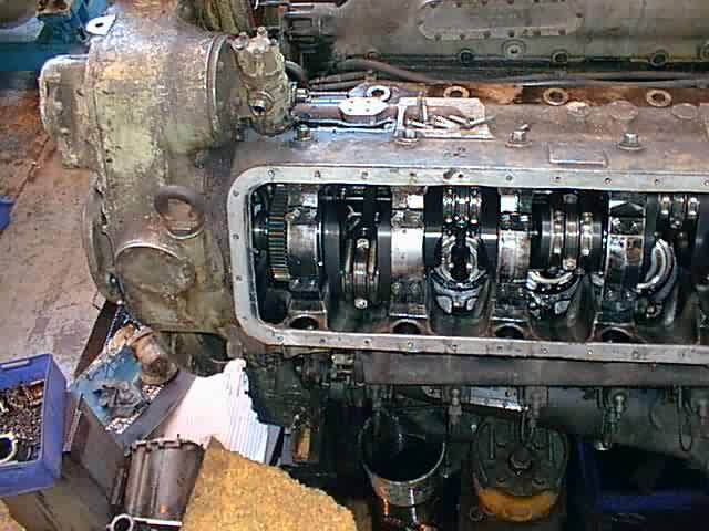
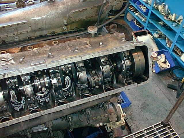
1847 - Photo: MAN B&W Paxman & courtesy of Michael Timms.This view show the generator end of the power unit with the crankcase covers removed. At this stage the crankshafts, con-rods and pistons are still in position. To the left of the crankcase is the phasing gearcase which was later removed, leaving just the basic triangle...
1846 - Photo: MAN B&W Paxman & courtesy of Michael Timms.This view of 9016's power unit at Paxman Diesels at Colchester show graphically the very thorough work being undertaken on the rebuild. The picture shows a general view looking down on the unit with the crank case cover removed. This was taken before any of the pistons had been withdrawn from the cylinders...
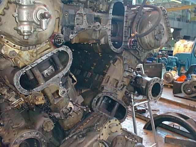
1845 - Photo: MAN B&W Paxman & courtesy of Michael Timms.This photo shows the power unit from the collector drum end. Here the exhaust collector drum and scavenge blower have been removed, making it possible to see inside the power unit to the cylinder liners, and of course exposing the triangle arrangement of the cylinder banks. The top left of this picture shows the hand barring over tool which is still attached to the end of the crankcase...
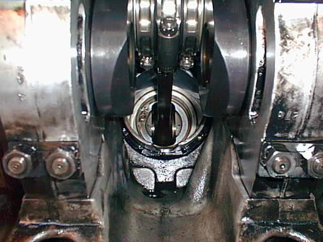
1844 - Photo: MAN B&W Paxman & courtesy of Michael Timms.This view shows the good internal condition of the power unit. At the top of the picture is the crankshaft and big end assemblies for the two separate cylinder banks served by this crankshaft. In the middle of the picture can be seen the small end of the con-rod attached to the end of the piston. The two items at each side of the picture are the end caps which hold the crankshaft in position. All of these end caps have bearing surfaces on them which rub directly onto the crankshaft...
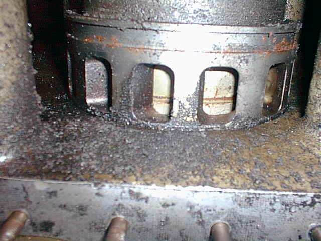
1843 - Photo: MAN B&W Paxman & courtesy of Michael Timms.This close up view shows one of the cylinder liners with a piston visible showing through the exhaust inlet holes (these ports being angled to make the inlet air swirl around the cylinder). It can be seen in this view that the piston rings are showing signs of corrosion due to the fire brigade's foam.