|
|
|
|
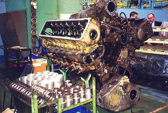
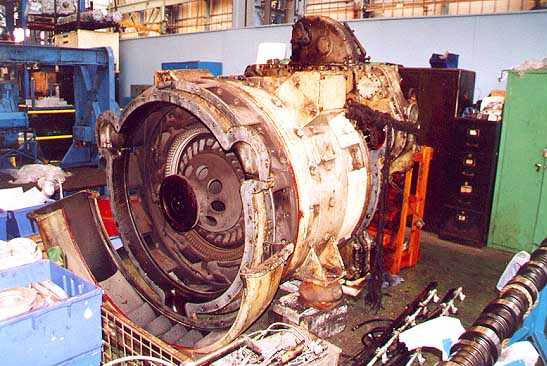
After a few more weeks of stripping down the basic triangle of 9016's power unit stands on the floor at Paxmans at Colchester. This end of the power unit is where the exhaust collector drum and scavenge blower were fitted. To the left of the unit in racks, lie some of the components removed from the unit during its strip down...
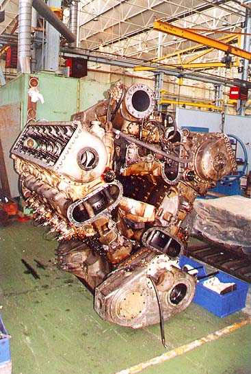
1857 - Photo: David Dimelow & courtesy of Michael Timms.This view shows the other end of the now heavily stripped power unit. The gutted crankcases can clearly be seen, as can some of the cylinder liners where the scavenger blower has been removed. At the top of the power unit on of the exhaust manifolds is still in place, although the lower two have already been removed...
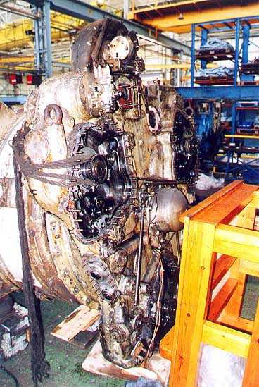
1856 - Photo: David Dimelow & courtesy of Michael Timms.Stored in another part of the works is the phasing gearcase which has been removed from the generator end of the power unit. As can be seen, this end of the gearcase is the one that attaches onto the crankcases. At the top of the gearcase can be seen the primary drive for the fan-drive prop shafts...
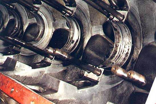
1855 - Photo: Michael Timms.At first this picture is difficult to visualize, but this is a close up view of one of the crankcases without the crankshaft and end-caps in place. The crankshaft rests against the circular bearings and is held in place by the end-caps and bearings which are bolted onto the long shafts which protrude from the crankcase casting...
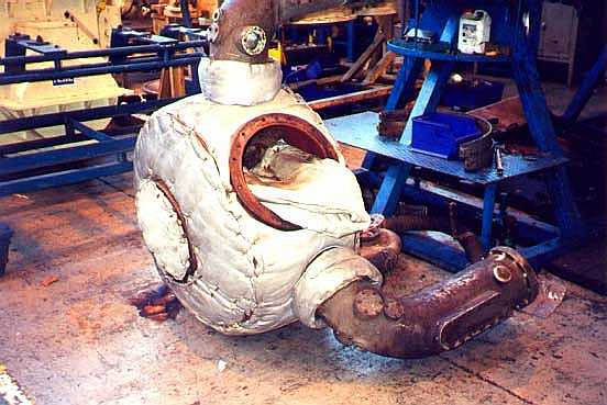
1854 - Photo: David Dimelow & courtesy of Michael Timms.The generator from 9016's power unit has been removed from the rest of the unit whilst the overhaul work is in progress. This view shows the air ducting end of the generator on the floor at Paxman's works. The circular flange in the centre of the generator attaches to the phasing gearcase when the power unit is assembled. Cooling air circulates into the generator from the loco's roof section into this area of the power unit when in use...
1853 - Photo: Michael Timms.This is the collector drum and elbow joints of the exhaust manifolds from 9016's power unit. The collector drum on the Deltic power unit can be the starting place of an exhaust fire due to the build up of carbon deposits, however in 9016's case the fire occurred in the silencers in the roof section due to the large amount of carbon which had not been cleaned from the exhaust system...
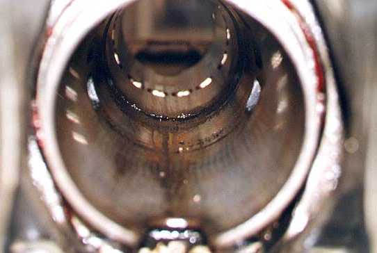
1852 - Photo: David Dimelow & courtesy of Michael Timms.This is the view right into the heart of 9016's power unit. The cylinder liner is seen with both pistons removed. The sticky mark towards the centre of the cylinder is where the pistons were stopped after the fire occurred. The ingress of fire retardant foam caused these marks in the cylinder liner. These liners are to be removed from the power unit and honed out to allow them to accept the pistons which will be re-fitted with new piston rings. The honing out of the liners will prevent most of the carry over of oil which is associated with these 2-stroke engines...
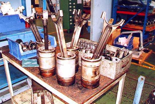
1851 - Photo: David Dimelow & courtesy of Michael Timms.The five culprits! These are the five damaged pistons which were part of the reason for this power unit from 9016 seizing up. Each one of them shows signs of corrosion caused by the ingress of foam. The corrosion has caused the piston rings to stick and rust, plus the main body of the pistons has chemical contamination which is still eating away at the aluminium body of each piston.